This tutorial covers wiring and mounting avionics components, flashing PX4 firmware and loading configuration parameters, ESC calibration and actuator testing, RC controller and telemetry radio setup, control surface linkage and verification, sensor calibration (compass, gyroscope, level horizon, autopilot orientation), flight mode and kill switch configuration, and pre-flight checks and safety considerations.
Time Required: 4-6 hours for a complete build and configuration
Prerequisites
Required Hardware
Airframe:
-
FliteTest Spear (or similar foam board flying wing)
-
Available at flitetest.com
Flight Controller:
-
Holybro Pixhawk 6C (or compatible Pixhawk-series controller)
Power System:
-
4S LiPo battery, 2200 recommended (3S is also compatible; this build uses 4S at ~15V)
-
Power Module (PM02 or equivalent) for battery monitoring
-
FT Power Pack c Radial v.2 from FliteTest
Control Components:
-
RC transmitter and receiver (Ghost radio, FrSky, or similar)
-
Propeller appropriate for your motor (pusher configuration)
-
Control rods/pushrods and clevis connectors (have spares, they can go missing)
Telemetry & Navigation:
-
GPS module (M8N or M9N with integrated compass)
-
SiK Telemetry Radio pair (915MHz for US, 433MHz for EU)
Miscellaneous:
-
Velcro strips for mounting
-
Servo extension wires
-
Allen wrench / hex key set (for propeller nut)
-
Small drill (for pushrod attachment holes)
-
MicroSD card for flight logging
-
USB cable for configuration
Required Software
-
QGroundControl (QGC), from qgroundcontrol.com
-
PX4 Firmware, downloaded automatically through QGC or built from source
Part 1: Frame Assembly & Component Planning
Before diving into electronics, ensure your FliteTest Spear frame is fully assembled according to FliteTest’s build instructions. You can find detailed build guides on their website. The wing should be assembled with the center payload bay accessible, elevon control surfaces installed, and the motor mount prepared in a pusher configuration on the rear.
Planning Component Placement
The FliteTest Spear offers generous internal space, which is one of its advantages for autopilot builds. The great thing about this airframe is there’s tons of room, a big payload bay up front, and you can poke holes through the cardboard to route cables wherever you need them.

Place heavier components like the battery and flight controller to achieve proper center of gravity per FliteTest’s recommendations for the Spear.
Mount the Pixhawk 6C in the center of the fuselage. In this build, the Pixhawk is mounted with a 270° yaw rotation, meaning the arrow points to the left of the aircraft instead of straight forward. This is done intentionally so the side ports remain accessible within the Spear’s narrow fuselage. PX4 handles this through the Autopilot Orientation setting (ROTATION_YAW_270), which is configured during sensor calibration in Part 10. If you can mount the controller with the arrow pointing forward, that’s the default orientation and no software adjustment is needed.
Part 2: Mounting the Flight Controller & Wiring
Mounting the Pixhawk 6C
Velcro is the recommended mounting method for this build. It allows easy removal for maintenance, peripheral connections, and troubleshooting without damaging components or ripping things up. Apply Velcro strips to the bottom of the Pixhawk 6C, apply matching strips to the center of your fuselage floor, position the flight controller (in this build, rotated 270° for port access), and press firmly to secure.
Understanding Power Distribution
The power architecture is critical for a reliable fixed-wing build. The flight controller gets its power from the power module, which sits between the battery and the rest of the system. Connect the power module output to the POWER1 port on the Pixhawk 6C using the 6-wire cable. The ESC also draws power from the battery through the power module to drive the motor.
Battery → Power Module → Pixhawk POWER1 port
                      ↓
                     ESC → Motor
Servo Power: Why You Need a Separate BEC
Important: Never power your servos directly from the 5V coming out of your flight controller. If your servos pull too much current, your flight controller can shut off or never power on in the first place, and then your aircraft falls out of the sky, which is no bueno.
Use a dedicated 5V BEC (Battery Eliminator Circuit) for servo power. These are cheap and reliable on Amazon, fine for powering servos, though you wouldn’t want to use them for something like a dual radio. The BEC can draw power from the power module or be spliced directly to the battery. In this build, the ESC’s power leads connect directly to the battery, so the BEC was spliced into those same leads for simplicity.
Servo & ESC Connections
For a flying wing with elevons, connect servos and the ESC to the I/O PWM OUT port on the Pixhawk 6C. If you look at the side of the I/O PWM header on the board, you’ll see three pin labels printed for each channel:
-
S (Signal) · Yellow or white wire · Carries the PWM control pulse from the flight controller
-
+ (Positive) · Red wire · Carries voltage from the BEC power rail to the servo
-
− (Ground) · Black or brown wire · Completes the circuit
The red wire should always end up in the middle. The BEC feeds into the + rail on this same header, which is what actually powers the servos; the flight controller only provides the signal.
The default PX4 flying wing mapping is:
|
Output |
Function |
|
MAIN 1 |
Left Elevon |
|
MAIN 2 |
Right Elevon |
|
MAIN 3 |
Motor (Throttle) |
Plug your left elevon servo connector into the MAIN 1 channel, your right elevon servo into MAIN 2, and the ESC signal connector into MAIN 3. The ESC signal connector typically has the same S/+/− wiring as a servo, but the ESC gets its main power from the battery, not from the servo rail. The ESC power leads connect to the power module or directly to the battery.

Once, you’re done, clean up your wires and secure them where possible. Then we can move onto flashing the firmware onto the flight controller.
Part 3: Flashing PX4 Firmware & Loading Parameters
With hardware connected, it’s time to configure the flight controller.
Connecting to QGroundControl
Download and install QGroundControl from qgroundcontrol.com. Connect the Pixhawk 6C to your computer via USB, and QGC should automatically detect the flight controller.
Flashing Firmware
In QGC, click the Q icon (application menu) and go to Vehicle Configuration then Firmware. This is when you plug in the flight controller, and QGC will detect it.

Click on PX4 Pro v1.16 Stable Release for the most recent firmware as of this tutorial. Optionally, if testing with custom firmware like we did, click Advanced Settings then Custom firmware file, select your firmware file (in this build, PX4 v1.17.0 beta), and click OK. The firmware will flash to the board and the flight controller will reboot automatically.

Loading Configuration Parameters
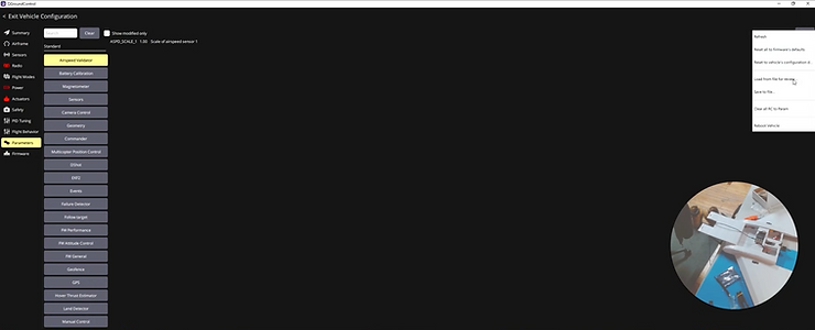
If you have a pre-configured parameter file, go to Parameters, then Tools, then Load from file. Navigate to your downloads folder, select the parameter file, and click OK to load. You may have to rename this text file to flitespear.params on your side.

Handling Parameter Mismatches:

When loading parameters from a different PX4 version (for example, loading v1.16 parameters onto v1.17 firmware), you may see warnings about missing parameters. There are a few things that could be happening. Those parameters might not exist anymore in the new version. They might not have been enabled because the vehicle configuration was different; for example, the Pixhawk may have had a different airframe type configured previously, so now that the vehicle configuration has changed, some parameters will show up on the next load. Or they may simply be deprecated, in which case don’t worry about them too much.
After loading parameters, QGC will prompt you to reboot the vehicle. Unplug and replug the USB connection. If you still see parameter warnings after rebooting, load the file again.

You’ll likely see fewer mismatches now that the vehicle configuration is set. Some parameters just might not exist anymore, and that’s okay. You can review the remaining mismatches and decide which ones to keep or skip. Parameters related to PWM min/max values are important to get right; others that are clearly from a deprecated feature can be ignored.
Tip: After resolving all parameter mismatches from a version upgrade, save a clean parameter file for the new version. In QGC, go to Parameters, then Tools, then Save to file. That way, when you or someone else flashes v1.17 onto the same vehicle type in the future, you can load the parameters cleanly without any warnings.
Part 4: Actuator Testing & ESC Calibration
⚠️ CRITICAL: Remove all propellers before actuator testing!
Before connecting control surfaces, verify that all actuators respond correctly.
Initial Actuator Check

Connect battery power to the aircraft and go to Vehicle Configuration then Actuators.
You should see your actuator outputs mapped: Left Elevon, Right Elevon, and Motor. Give the system power (~15V on a 4S battery) and you should hear the servos move as they initialize. That’s a good sign.
Tip: When testing actuators on the bench, use the QGC Actuator sliders rather than the RC transmitter. This avoids accidentally arming the vehicle or triggering a mission mode from the RC. In this build, the RC controller nearly triggered a mission accidentally, so the switch was made to QGC sliders for safety. Go to Vehicle Configuration then Actuators and use the test sliders at the bottom of the page.
ESC Calibration
⚠️ CRITICAL: Remove all propellers before ESC calibration and motor testing!
The ESC needs to be calibrated before the motor will respond properly. If you try to spin the motor without calibrating first, nothing will happen. That’s how you know the ESC hasn’t been calibrated yet.

To calibrate, first unplug the battery from the aircraft while keeping the flight controller powered via USB. Go to Vehicle Configuration then Power and click Calibrate. When prompted, connect the battery. Listen for ESC confirmation beeps, and the calibration will complete automatically. Unplug when prompted.

Important: If you ever change the physical pin assignment for the motor, you must recalibrate the ESC afterward.
Testing the Motor
After ESC calibration, go back to Vehicle Configuration then Actuators, find the Motor slider, make sure no propeller is attached, and slowly increase the slider value. The motor should spin. Verify it spins in the correct direction: for a pusher configuration, it should push air toward the rear of the aircraft.
Testing the Servos
Test each servo individually. In the Actuators panel, find the Right Elevon slider. Move it and put your finger on the servo; you should feel it move. Repeat for the Left Elevon.
Troubleshooting Incorrect Mapping:
If you move one of the Elevon’s slider but nothing happens (or the wrong servo moves), your pins are mapped incorrectly. You have two options: change the output assignments in the Actuators panel (software fix), or physically move the servo connections to the correct pins (hardware fix). If you go the hardware route, remember to recalibrate the ESC afterward since the motor output may have changed.

After verifying, the Right Elevon slider should move the right servo, the Left Elevon slider should move the left servo, and the Motor slider should spin the motor.
Part 5: RC Controller Setup
Connecting the RC Receiver
Connect your RC receiver to the appropriate port on the Pixhawk. For this build, we’re using a Ghost radio connected to the RC input port.
Verifying RC Connection

Go to Vehicle Configuration then Radio. You should see the channel indicators on the right side of the screen. Wiggle the sticks on your transmitter to confirm the connection. Once you see those indicators responding, you know the RC is connected.
RC Calibration
Click Start Calibration and make sure the throttle stick is all the way down, as shown in the diagram. Click Next, then move all sticks through their full range as prompted. Toggle all switches, then click Next and Finish.
Part 6: Telemetry Radio Setup
Telemetry radios enable wireless communication with your ground station for real-time data and command capability. This is how MAVLink packets flow between the drone and QGroundControl.
Hardware Connection

Connect the vehicle radio to the TELEM1 port on the Pixhawk 6C, mounting it with clear antenna exposure and away from the ESC. Connect the ground station radio to your computer via USB. Default settings work for most applications, with the TELEM1 port talking at a 57600 baud rate.
Updating Telemetry Radio Firmware (Optional)

People don’t always know this, but you can actually update the firmware on telemetry radios through QGC. Disconnect from the vehicle first, then go to Vehicle Configuration then Firmware. Connect the telemetry radio via micro USB, and QGC will detect it as a “SiK Radio.” Follow the prompts to flash the firmware; it will download and upgrade automatically. Repeat for the second radio.
Establishing Telemetry Connection

Connect the ground radio to your computer and power the aircraft with the actual battery (not just USB) so you can verify it’s not just the USB MAVLink connection. In QGC, the connection should establish automatically and parameters will load, which may take a moment.
Note on Radio Proximity: When the radios are very close together, they can create noise because they’re essentially shouting at each other over what should be a long distance. Getting a little bit of space between them helps during bench testing. If parameters are loading slowly or you see connection issues, separate the radios by a few meters.
How Control Flows: Telemetry vs. RC
Understanding the split between telemetry and RC is important. Autonomous missions are uploaded to the drone via the telemetry radios from QGC. When you plan a mission, it uploads through these radios. Manual override is performed via the dedicated RC transmitter (the Ghost radio in this build), which operates on its own separate link.
You can plug in a USB joystick (like a Logitech controller or Xbox controller) directly into your computer and send manual control commands over the telemetry radios. However, a dedicated RC transmitter is preferred because it doesn’t share bandwidth with telemetry data and provides lower latency for manual inputs. You don’t want your manual joystick commands to have latency or get clogged out if the telemetry traffic increases.
Optimizing Telemetry Bandwidth

You can adjust the MAVLink streaming mode in QGC to control how much data flows over the telemetry link. If you look at the MAVLink mode setting (for example, “MAV 0 mode”), you can change it to a minimal mode. This reduces the volume of telemetry messages, which is useful when you need responsive manual control over the same link. If you want to do manual control over the telemetry radios, changing to a MAVLink mode that doesn’t send as many messages means your manual controls will go through more reliably.
Part 7: GPS Mounting
Mounting Location

Mount the GPS module where it has a clear sky view, distance from power wires and the ESC to reduce magnetic interference, and stable, vibration-free mounting. For the Spear, the GPS was mounted up front, with the cable routed down through the airframe and plugged into the GPS1 port. The telemetry radio was moved to the back, and the RC antenna was routed out to one side.
Antenna Placement Considerations
Be mindful of antenna placement relative to power electronics. Keep RC receiver antennas away from the ESC. Radio signals and power don’t mix well; you don’t want to put any antennas or really anything that you’re doing with radio next to power. Route antennas to minimize interference.
For a budget build like this ($40 airframe), some compromises are acceptable, but try to maintain separation where possible. A bit of tape to keep wires from touching power components helps.
Optional RTK GPS: If you’re using an RTK GPS module for higher-precision navigation, route the RTK antenna with the same interference considerations. In this build, the RTK antenna was routed out to one side of the airframe, away from the ESC and power lines.
Part 8: Connecting Servos to Control Surfaces
Now it’s time to mechanically link the servos to the elevons (the control surfaces, sometimes called flaperons on a flying wing).
Understanding Servo Neutral Position
Before connecting linkages, you need to establish the servo’s neutral (disarmed) position. Power the aircraft, and with it disarmed, the servos will sit at their neutral position. In QGC Actuators, you’ll see minimum 800, maximum 2100, and the disarmed value right in the middle at 1450. You can double-check by going to the Q icon, then Analyze Tools, then MAVLink Inspector, scrolling down to SERVO_OUTPUT_RAW, and confirming both servo outputs read approximately 1450µs.
Installing Control Rods
The airframe kit should include pushrods, but they may go missing. In this build, the rods had to be purchased separately, and small holes were drilled for attachment. Having spare pushrods and a small drill on hand is recommended.
For each control surface:

-
Ensure the servo is at its neutral position (aircraft powered but disarmed).
-
Position the elevon level with the wing. This is what you want when disarmed. The best way to do this is to power the UAV and make sure nothing is connected to the control surfaces, so the servos sit at their neutral state.
-
Attach the pushrod to the servo arm, keeping the arm roughly perpendicular to the pushrod with no offset.
-
Adjust the pushrod length so the control surface sits level when connected.
-
Attach to the control horn on the elevon by threading through the control horn hole and securing with a clevis keeper.
-
Secure the control horns with screws on top, so they don’t pop off mid-flight.

Pro Tip: Position the plastic clevis retainer (the “tooth”) on top of the control horn. That way if it becomes unhooked, it doesn’t fall out and disconnect mid-flight. It’s all about making sure things don’t come undone in the air.
Alignment Tips
Both elevons should be level with the wing when disarmed. That’s what you’re looking for. If you can’t get perfect alignment, bias slightly upward. You’d rather have a slight climb tendency than a dive, especially on launch. That way when you release the sticks and the aircraft is flying level, at least you’re going up instead of flying down. The linkage rods on both sides should be roughly the same length for consistent response.
Repeat the process for both sides, ensuring the disarmed position has both surfaces level with the wing. Then give each servo a whirl and test it up and down to confirm the range of motion.
Part 9: Control Surface Verification
This is a critical step. Verify that stick inputs produce the correct control surface movements. You have everything installed; now you want to make sure that everything is mapped correctly.
How Flying Wing Controls Work
On a flying wing like the Spear, the elevons combine the functions of elevators and ailerons.

For pitch (elevator function): pulling the stick back raises both elevons, which causes the airflow to push the back of the wing down, making the nose pitch up. Pushing the stick forward lowers both elevons, causing the back of the wing to pop up and the nose to pitch down.

For roll (aileron function): moving the stick left raises the left elevon and lowers the right, which pushes the left wing up and causes the aircraft to roll left. Moving the stick right does the opposite, raising the right elevon and lowering the left.
Flying wings have minimal yaw authority since they lack a rudder. Yaw is managed through differential drag on the elevons. For a budget build like this, precise yaw response isn’t a major concern, but you should at least verify the response direction is correct if your configuration includes yaw mixing.
Testing Control Response
Power the aircraft and use the RC transmitter sticks to test (or arm in stabilized mode). For pitch, pull back on the stick and confirm both elevons raise, then push forward and confirm both lower. For roll, move the stick left and confirm the left elevon goes up while the right goes down, pushing the left wing up and causing a roll to the left. Then move stick right and verify the opposite response.
What to Do If Controls Are Reversed
If a control moves opposite to what’s expected, go to Vehicle Configuration then Actuators, find the reversed servo, check the “Reverse” option for that output, and test again.
Give everything a final test. Move through the full range of motion and make sure nothing is popping out or binding unexpectedly. Once you’re confident all servos are mapped correctly, move on to calibration.
Part 10: Sensor Calibration
With control surfaces verified, the next step is calibrating the onboard sensors. The vehicle will not arm without completing these calibrations.
Autopilot Orientation
If your flight controller is not mounted with the arrow pointing straight forward (as in this build, where it’s rotated 270°), you need to tell PX4 about the rotation. Go to Vehicle Configuration then Sensors and click Set Orientations. Set the Autopilot Orientation to the correct value.
In this build, the orientation is set to ROTATION_YAW_270 (270°). Here’s why: looking at the aircraft from above, 0° is the nose (forward), 90° is the right side, 180° is the tail, and 270° is the left side. Since the Pixhawk’s arrow points to the left of the aircraft, that’s 270°. This is done intentionally so we can access the side ports within the Spear’s fuselage.
Level Horizon Calibration

Place the aircraft on a flat, level surface and make sure it’s truly level. In Vehicle Configuration then Sensors, click Level Horizon. Keep the aircraft still while it calibrates. This is quick and easy.
Gyroscope Calibration

In Vehicle Configuration then Sensors, click Gyroscope. Keep the aircraft completely still on the level surface. The calibration completes in a few seconds.
Compass Calibration

This is the most involved sensor calibration. In Vehicle Configuration then Sensors, click Compass. QGC will prompt you to rotate the aircraft through several orientations. Start with the nose pointing up and rotate slowly. Then flip upside down and rotate again. You don’t have to do a perfect full 360 in every orientation, but it helps to cover as many angles as possible.

If you’re still connected via USB, the cable will limit your range of motion. You won’t be able to do full 360-degree rotations, but do the best you can. Partial rotations still provide useful calibration data.

Compass Sanity Check
After calibration, do a quick sanity check. Look at the compass heading displayed in QGC and point the aircraft in a known direction (for example, south) to verify the heading reads approximately correct. Then set the aircraft down and watch the compass heading. It should be stable. If the heading is wandering all over the place or slowly drifting while the aircraft is stationary, there may be a magnetic interference problem. Check for power wires or motors too close to the compass.
Part 11: Flight Mode & Kill Switch Configuration
Before installing the propeller and doing final testing, configure your RC switches for flight modes and safety.
Mapping Flight Modes to RC Switches

In QGC, go to Vehicle Configuration then Flight Modes and assign your RC transmitter switches to different flight modes. At a minimum, you should be able to switch between Stabilized mode (the autopilot levels the aircraft but you control throttle and direction), Manual mode (full manual control with no autopilot assistance), and Mission mode (autonomous waypoint following).
The critical principle: always have a fallback. If you’re testing out Mission mode, make sure you can fall back into Manual mode or Stabilized mode with a flick of a switch. Verify that switching modes on the RC transmitter is reflected in QGC.
Configuring a Kill Switch

A kill switch immediately disarms the motors. It’s a last-resort emergency stop. In Vehicle Configuration then Flight Modes, assign one of your RC switches as a Kill Switch. Test it by flipping the switch and verifying QGC shows the vehicle as disarmed.
The kill switch is especially important when testing hardware for the first time. Obviously, you want to be very careful with it. If you’re airborne, killing the motors means the aircraft falls. It’s a very last resort, emergency-type deal. But having it configured and accessible is essential for safe testing.
Testing Mode Switching
Before going further, cycle through each flight mode using your RC switches and confirm QGC displays the correct mode for each switch position. Confirm the kill switch works and that you can recover from the kill switch back to a normal mode.
Part 12: Propeller Installation & Final Checks
We’re going to mount the propeller, make sure it’s spinning the right way, and get ready for a test flight.
Motor Direction Verification

Before installing the propeller, verify motor direction using the QGC Actuator sliders (not the RC, to avoid accidentally arming into a flight mode). Go to Vehicle Configuration then Actuators and use the motor test slider. Note which direction the motor spins.
For a pusher configuration (motor at the rear, like the Spear), you want wind to blow out the back. Think through it: if the motor spins a certain direction, it’s going to take air and push it out the back. That’s what you want.
Selecting the Correct Propeller
The propeller must match your motor’s rotation. For a pusher configuration, you need a pusher prop (reverse pitch compared to tractor props) that moves air toward the rear when spinning. Check the prop markings, as pusher props are often labeled with “R” or “Pusher.” The props in this build had a high attack angle.
Installing the Propeller
Select the appropriate prop adapter or collet for your motor shaft. Try the included O-rings or spacer rings to find the one that fits best, because you want it tight. Slide the propeller onto the shaft and tighten the prop nut securely with an allen wrench (you’re going to want one, so don’t be caught without the right size).

Important: Make sure the propeller is tight. A loose prop is dangerous and can damage the motor.
Final Motor Test
⚠️ Keep hands and body clear of the propeller arc! Is this dangerous? Yeah, but there are more dangerous things you can do. Still, be careful.
Secure the aircraft, power it with the battery, and give it a little gas using the QGC Actuator motor slider. Verify that the motor spins smoothly, you feel thrust pushing toward the rear with wind coming out of the back, and there are no unusual vibrations.
Battery Installation
Place the battery in the nose area, right in the battery bay, and secure it with Velcro. Just lock it down in there. Alternatively, you can make some holes and put straps if you prefer. Verify CG per FliteTest’s specifications for the Spear and route the battery wire away from the propeller and control surfaces.
Pre-Flight Checklist
Before your first flight, complete this checklist:
Mechanical
-
[ ] All control surfaces move freely
-
[ ] Linkages secure with no slop
-
[ ] Control horns screwed down
-
[ ] Propeller tight
-
[ ] Battery secured at proper CG
-
[ ] No loose wires
-
[ ] No wires or or other obstructions near the motor/propeller
Electronics
-
[ ] Telemetry link established
-
[ ] GPS has satellite lock
-
[ ] RC transmitter connected
-
[ ] All sensor calibrations complete (level horizon, gyro, compass)
-
[ ] Compass heading stable and accurate
Flight Modes & Safety
-
[ ] Flight modes switching correctly via RC switches
-
[ ] Kill switch configured and tested
-
[ ] Fallback mode verified (can switch from Mission to Manual/Stabilized)
-
[ ] Failsafe configured
Controls
-
[ ] Pitch: stick back = both elevons up
-
[ ] Roll: stick left = left elevon up, right down
-
[ ] Throttle increases motor speed
-
[ ] Elevons return to neutral when sticks centered
First Flight Tips
Choose calm conditions with wind under 5 mph for first flights. Find an open area with
plenty of room for mistakes. Start in Stabilized mode, which provides attitude assistance. Keep it close and stay within comfortable visual range. Know your failsafes and understand RTL behavior.
Arming
Ensure there are no errors in QGC. Move the throttle stick to the bottom-right corner (yaw right), or use an arming switch or QGC arming command. The aircraft is now live, so be ready.
Hand Launch
Hold the aircraft at shoulder height with the nose slightly up. Apply roughly 75% throttle, throw firmly forward, up at a 30 degree angle, and immediately climb to a safe altitude.
Troubleshooting
Motor Won’t Spin After ESC Calibration
Verify the correct output is assigned to the motor and check the ESC signal wire connection. Try recalibrating the ESC. If you changed pin assignments, you must recalibrate.
Servos Don’t Move
Verify the BEC is providing power and check servo connections. Test in the Actuator panel.
Telemetry Connection Drops
Separate the radios by several meters and check antenna connections. Verify matching firmware versions on both radios. Try reducing the MAVLink streaming rate for less bandwidth contention.
Control Surfaces Move Wrong Direction
Use the Reverse checkbox in the Actuators panel and verify linkage geometry. For flying wings, ensure elevon mixing is configured correctly.
Airspeed Check Warning
This build does not include an airspeed sensor. You may see “airspeed check” warnings in QGC. For a basic build, you can disable the airspeed check by setting the CBRK_AIRSPD_CHK parameter to 162128, or by setting FW_ARSP_MODE to disabled. For more advanced autonomous operations, an airspeed sensor is recommended.
Compass Wander
If the compass heading drifts or wanders while the aircraft is stationary, check for magnetic interference from power wires, motors, or the ESC mounted too close to the GPS/compass module. Increase separation and recalibrate.
Resources
-
PX4 Documentation: docs.px4.io
-
QGroundControl Guide: docs.qgroundcontrol.com
-
Holybro Docs: docs.holybro.com
-
FliteTest: flitetest.com
This tutorial was created by Ascend Engineering. Happy flying!